Software architecture and project design, a mechanized approach
Motivation
Architecture is a unique area of software development where there don’t really seem to be any industry standards. Considering how much software developers love to automate processes for efficiency, this seems surprising.
The goal of this post is to demystify the topic of software architecture, and present my personal favorite methodology for approaching software architecture with a mechanized approach that can be applied to any project.
This is a very large topic so this post is going to cover a lot of information very quickly. I intend to follow up this post with more content where I can expound on pieces of this method in more detail or provide more background as to why it’s important, so keep an eye out for those in the future. Questions and feedback is always welcome!
Alright, lets dive in then.
So what is software architecture anyway?
Before we dive into the methodology, I want to address this question.
There are many things that are related to or a part of software architecture that might immediately come to mind: design patterns, functional decomposition, requirements gathering, server infrastructure, selecting tools and technologies, etc. These are all important things, and many of them play a role in software architecture, but don’t necessarily define it. This is my current favorite definition of software architecture:
Software architecture refers to the high level structures of a software system, the discipline of creating such structures, and the documentation of these structures. These structures are needed to reason about the software system. Each structure comprises software elements, relations among them, and properties of both elements and relations.
Quote from “Documenting Software Architectures: Views and Beyond, Second Edition”
Software architecture then, is the process of decomposing a system into structures, and creating documentation of these structures.
If that sounds extremely similar to the architecture of a building, that’s because it is. The process of software architecture should result in a deliverable, and that deliverable is the blueprints of the system.
In building architecture, many blueprints will be created depicting the same building from different contexts. One blueprint might depict the electrical system, while another depicts the placement of the walls, doors, and windows. Software architecture is no different. You should create many different diagrams which depict the same system from different contexts. Software architecture diagrams look quite different from building blueprints, but we’ll get to those later.
Influences
The method I am describing in this post is heavily influenced by Juval Lowy’s “IDesign” method. To my knowledge, this method is IDesign as best as I can explain it, but having never taken Juval’s class myself, I can only assume I’m filling in the blanks correctly. After reading this post, if you feel like you’d like to pursue this method further and take a class from the master himself, head over to IDesign.net. There you will also find download links for official documentation, and a link to the IDesign YouTube channel.
The method
The method consists primarily of two disciplines
- Decomposing the system into useful abstractions
- Creating diagrams to document the system.
We’ll start with #1
Volatility-based decomposition
Volatility-based decomposition is guiding principle of this method. So what is it? Before I answer that, I’d like to specifically point out what it isn’t.
It isn’t functional decomposition
Many of us have heard of or possibly even performed a functional decomposition of a software system. If the requirements of a system are that it is able to do A, B, and C, then you’d decompose the system by creating an A service, a B service, and a C service.
So what have we accomplished here? Did we do architecture?
Not really. If that felt very simple, that’s because it was. Typically, identifying the functional requirements of a system is quite easy. In many cases, these requirements are provided to you in advance. So when you take requirements, and create software services that map essentially one-to-one with the requirements, you really aren’t putting much thought into the abstractions you’re creating.
So why is this problematic?
Because requirements change.
Architecture is the highest level of abstraction in a system, and therefore is the most difficult aspect of a system to change.
See the problem?
With functional decomposition, you’re rigidly coupling the architecture of a system to the current requirements. And I’ll say it again, requirements change. They always change. It’s inevitable. No reasonably complex piece of software has ever existed without being maintained and updated over time to satisfy new requirements. In many cases, requirements change before a system is even complete.
When you couple your architecture to requirements, the system becomes rigid, and rigid systems are difficult to change in the kind of fundamental ways typically necessitated by changing requirements.
So what should you do instead of a functional decomposition? You guessed it. Volatility-based decomposition.
Volatility-based decomposition means you encapsulate pieces of the system that are likely to change
So how do you know what’s likely to change? Great question. I wish I could provide a concise concrete answer to that question that would apply to all projects, but of course, such an answer doesn’t exist. All systems have different requirements, and all systems are likely to change in different ways. I can, however, provide a bit of direction.
Consider the two main axes of volatility
- At one moment in time, what is different between how two different customers interact with the system?
- Over time, how is one customer’s interaction with the system likely to change?
Another tip: when considering what will change, keep your considerations bounded to the business domain. By that I mean, if you’re designing a system for selling stocks, don’t worry about what happens if the same company decides to start delivering pizzas. It’s too far outside the business domain to worry about. If an event like that occurs, you’ll be designing a whole new system.
What does this really mean?
Some concrete examples of areas of volatility:
- If your system sends notifications to users, the delivery method might change. Perhaps you start with email and later change to SMS
- Create a notifications service
- If your system accepts electronic documents for processing, consider the possibility of receiving a new file type or a new standard
- Create a mapping service to standardize incoming documents
- If your system stores data, the storage method is likely volatile. You might switch storage methods entirely, or implement caching
- Expose your data with a service
These are just a few examples, and they’re somewhat generic because there will always be domain-specific or project-specific areas of volatility.
How do I turn this into a deliverable?
Now that you’re looking at a system from a different perspective so you can split it into abstractions which encapsulate areas of volatility, how exactly do you turn that into deliverable architecture? We were talking about diagrams right? So let’s find out what those look like.
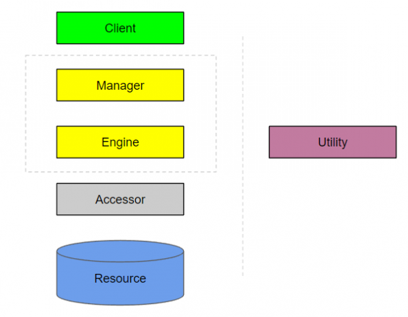
These are the building blocks of your architecture, and this hierarchy of abstractions can even be directly translated into the actual structure of your project’s source code. You will be using these blocks in multiple diagrams as you document the system from different contexts.
Lets meet the building blocks!
Clients
A client is an entry-point into the system. It can take many forms. If your system has a user interface, that user interface will be part of a client.
If your system is web-based, a client might be an entire MVC website, at least as far as rendering the views and responding to user requests is concerned. More on this later.
An HTTP REST API endpoint can be a client.
A mobile application can be a client.
A client can also be extremely thin. Perhaps your system is automated and runs as a Windows Service. The Windows Service would be a client.
You may be asking yourself, how can an entire website or mobile app be just an entry point?
As soon as your client needs to do anything other than manage the user interface, it calls a Manager.
Managers
Managers encapsulate the volatility of workflows. They own the sequence of events. They are the puppet masters, orchestrating the work done by all the layers below. As the highest level of abstraction for a given call chain, methods in Manager classes should be relatively lightweight and easy to read. Imagine describing a single piece of functionality of your system by listing the steps in plain English. The code in your Manager methods should read almost as simply as that plain English list of steps.
If that’s still a bit abstract, lets try a concrete example.
Say you have an e-commerce store presented as an MVC website. The MVC website is your Client, and as soon as your Client is ready to do actual work, say, submitting a customer’s cart to process an order, it’s going to call a method on a Manager.
So in this example, you’ll likely have an Order Manager that has the capability of executing the “Place an order” call chain. The work involved in executing that call chain can be listed in plain English like this
- Calculate shipping costs
- Calculate tax
- Apply discounts
- Write order information to order history database
- Update the remaining quantity of each item from this order in the inventory database
- Process the payment
- Send customer a receipt
This is how the code in the Order Manager should read! It really should be nearly that simple.
Each of those steps might have a significant amount of complex logic behind it, but that logic will exist in a lower level abstraction. The Manager is only making the calls in the correct order, with a minimal amount of control flow logic as needed.
Engines
Engines encapsulate volatility of a single process with a Manager’s sequence. Or to put that another way, Engines model polymorphism within a single step. In the previous example of processing an order, one of the steps was “Process the payment”. While the step is always described the same way — process payment — the details of how payments are processed vary between orders, assuming you support multiple payment methods. Charging a credit card is a very different process than integrating with PayPal, for example. This is polymorphism: the same step — process payment — has several different forms. Engines are an example of the strategy pattern. When there is runtime switching of implementation under a common interface, you have a need for an Engine.
Engines are optional
If you noticed on my building blocks diagram that Managers and Engines were both represented by yellow rectangles (and I even placed them together in a grey box), this is why. Engines are optional. With some call chains, there simply isn’t any business logic. Many times a call chain doesn’t have polymorphic steps at all, and in these cases, there is no need for an Engine.
Engines are on the same level as Managers… sort of
If an Engine does exist, it is considered to be on the same level as the Manager, but it must always have its work orchestrated by the Manager. A Client can not call directly into an Engine, more of these rules later.
Accessors
Accessors encapsulate accessing data from a Resource. It doesn’t matter what the source of data is, be it a SQL server, DocumentDB, or even a 3rd-party API, the Accessor is an abstraction that hides the data access logic from the rest of the system.
The Accessor is usually the layer that most developers are already somewhat experienced with. You might already be familiar with the Repository pattern. If you are, this concept is going to seem very familiar to you, because it’s extremely similar.
It’s worth noting that a Resource isn’t always something contained in your system. If you’re calling a 3rd-party API as a source of data, this API is considered a Resource. Your Accessor should hide the implementation details of communicating with the API and only expose the data returned from the API in a way that is meaningful to your system.
Resources
Resources are the actual sources of data encapsulated by an Accessor: SQL server, DocumentDB, Key/Value stores, Cache, Disk, etc.
And don’t forget about 3rd-party APIs!
If it provides data to your system, it’s a Resource, and it needs to be encapsulated by an Accessor.
Utilities
Utilities encapsulate cross-cutting concerns. They don’t exist as a hierarchical layer of the system, they exist along side it.
Any layer can call a Utility, which is why they’re depicted off to the side of my diagram.
A Utility is going to encapsulate concerns like logging and notifications; things that any layer of the system might need to do.
Cross-cutting concerns such as logging typically have popular libraries that become ubiquitous within each tech stack, but the Utility is still an important abstraction.
Much like the Accessor which exists to hide data access logic, a Utility exists to hide implementation details.
You could easily add your favorite logging library to each layer with a package manager, but then you’re not protecting yourself from the volatility of logging concerns. What if you needed to start logging to a database instead of to disk? Even if you had a nice configuration-based logging package you’d still need to update your logging configuration in all layers of the system.
Now you know the layers, so how do they interact? Time for some rules
Layers can only call down to lower layers
All calls should flow down from higher layers to lower layers.
An Accessor can not call an Engine. An Engine can not call a Manager. A Manager can not call a Client.
The exception is Utilities. All layers can call Utilities since these are cross-cutting concerns.
Don’t skip layers when calling down
A Client can only interact with the system through a Manager. A Client can not directly call an Engine, Accessor, or Resource.
A Manager can call an Engine or an Accessor. This is because Engines are optional, and even when an Engine is present, data access and business logic are not always coupled together in such a way that necessitates an Engine sitting between the Manager and the Accessor.
Engines can only call Accessors.
Accessors can only communicate with Resources.
Don’t share models between layers
The layers exist to encapsulate volatility, and when you share models between layers, you lose that protection.
For example, in the .NET world, Entity Framework is a very common library used to access data from a SQL server. Entity Framework returns what are called “Entities”, which are basic models decorated with annotations that help Entity Framework understand the underlying SQL schema. These annotations are data-access logic, and therefore the Entities themselves should never leave the Accessor. Even if your Accessor is going to return data in the exact same structure as your Entities, it is important to map these Entities to Data Transfer Objects before returning data from the Accessor.
Learn how to use an automatic mapping library. You’ll need it
This rule doesn’t stop at the Accessor layer either. Your Manager is often going to pass data from an Accessor to a Client, but it’s important to map the Data Transfer Object received by the Accessor to a new set of models that exists at the Manager layer before exposing this data to the Client. The models exposed by the Manager layer are referred to as Contracts.
No sideways calls either
An Accessor should never directly call another Accessor. If you need data from two sources, that should be orchestrated by a Manager or an Engine.
Engines should not directly call other Engines for the same reason, orchestrate this flow in a Manager.
And finally Managers can not call other Managers… sort of.
Not directly at least.
It is actually valid for a Manager to call another Manager indirectly, either via a queue or a publish/subscribe event stream.
If you find yourself wanting to have a Manager call another Manager directly, that is a very strong “code smell” that indicates you might not have thought through your system decomposition enough.
Show me what it looks like!
Alright, we know the theory, we know the building blocks, and we know the rules. Lets turn this into a deliverable. Time for some diagrams!
I’ll start with the simplest of them all
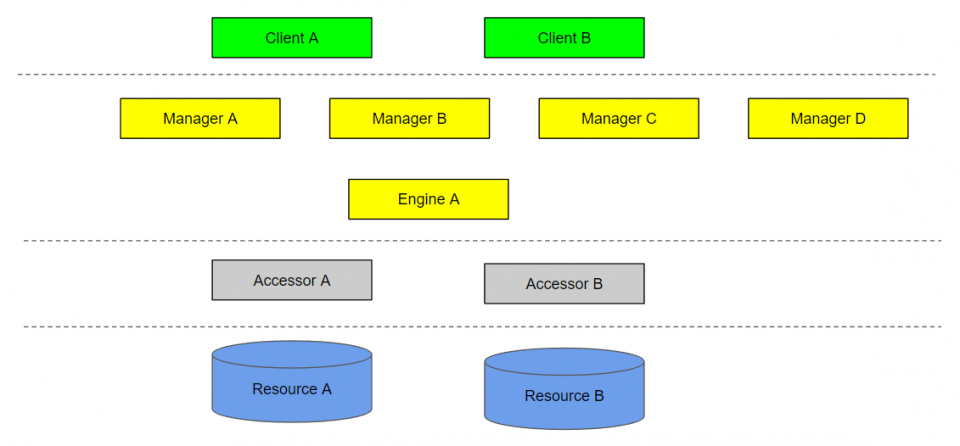
Static diagram
The static diagram is simply a depiction of all components in your system.
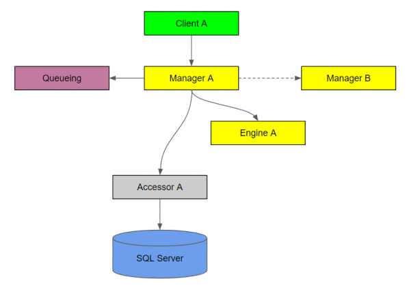
Call chain diagram
The call chain diagram depicts one call chain that your system is capable of, with arrows drawn to depict the calls.
A dashed arrow indicates an indirect call, either via a queue or publish/subscribe event stream.
You should create a call chain diagram for each capability of your system.
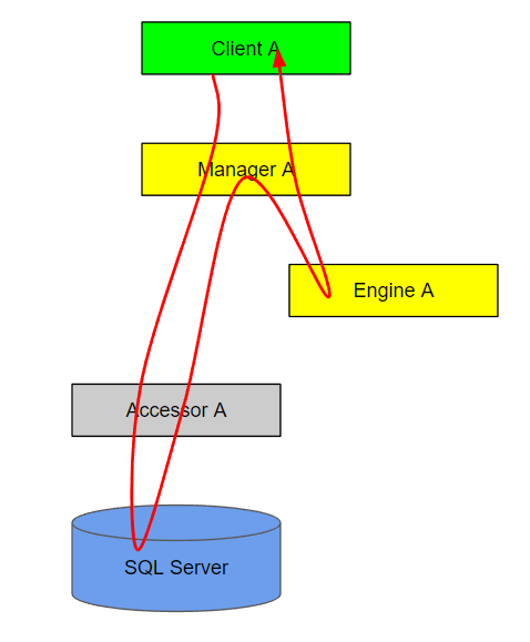
Synchronization diagram
This builds off the call chain diagram. A synchronization diagram depicts the flow of execution for a call chain.
If you can’t draw a diagram like this without tying a knot, then you likely need to introduce an indirect call to another manager via a queue or publish/subscribe event stream.
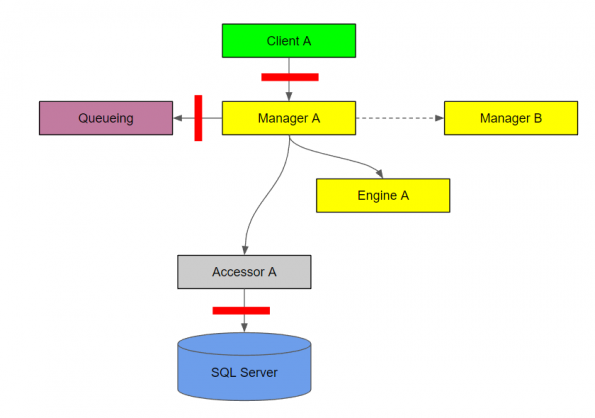
Authentication or authorization diagram
The red bars on this diagram indicate an authenticated or authorized call.
You can use a different color bar for authentication vs. authorization, but this is just a depiction of what either might look like.
It’s important to note that the diagram its self doesn’t depict the type of authentication or authorization is being used, only that it’s present.
The Accessor to Resource authentication might be integrated security with Windows authentication, while the authentication with the queuing Utility might be basic authentication.
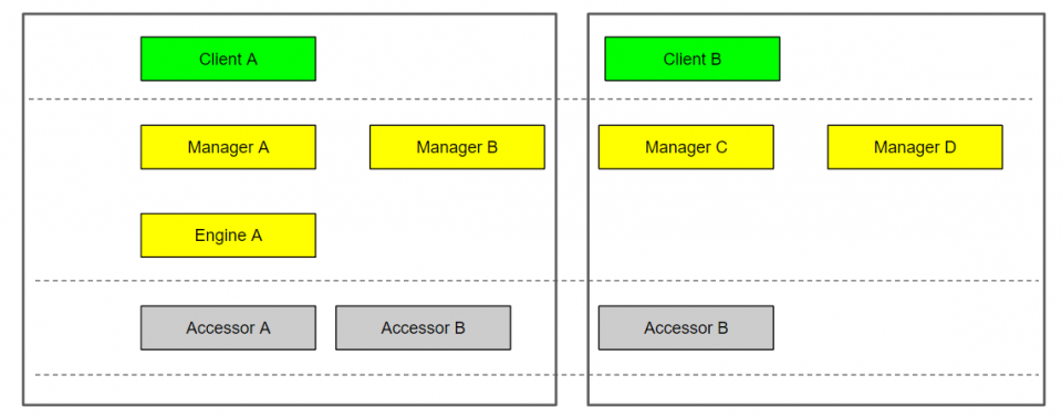
Process, Assembly, or Identity diagram
This diagram depicts which components of the system belong to which process, assembly, or has a certain identity. I’m showing one diagram here since they would all be depicted similarly.
This might be important if certain components of the system must run as isolated processes because of different availability requirements, or if the authorization mandated only certain parts of the system are available to certain identities.
Summary
This architecture method offers many benefits for teams of any size
Consistency
This method can be applied to any project, and in doing so, gives developers a common language and a familiar project structure.
Switching contexts can be extremely disruptive due to the significant amount of time it takes to familiarize ones self with a project’s structure. With a common naming convention and structure, switching projects becomes much less disruptive.
This method standardizes the documentation as well. I’d highly recommend checking your diagrams into source control alongside the code so every developer working on the project has everything they need on hand at all times.
Mechanization
This method allows for easy vertical slicing of the system.
An architect can create the project, stub out all the classes, interfaces, and method signatures, and pass off the documentation and source code for a team of developers to fill in the blanks. The developers can use call chain diagrams as independent tasks to complete.
Thoughtfulness
It’s easy to rush through architecture and jump straight into code when you’re only coding to the requirements, but by decomposing a system to identify areas of volatility you’re required to think critically and bring the pain to the forefront before any code is written.
This is not an easy process, because volatility is not self-evident. No product owner will ever tell you up front which requirements are going to change, because they’re only concerned with what they need right now.
This method of system decomposition takes considerably longer than functional decomposition as a result. An architect will spend entire days doing little more than thinking, but therein lies the power of the method.
Best practices are built in
Every developer strives to write loosely coupled code that is suitable for automated testing, but it’s not easy to do. This method forces you to decouple your components in fundamental ways that are beneficial for every project.
Pingback: clindamicina 150mg
Pingback: fluoxetine itching
Pingback: gabapentin availability
Pingback: half life of duloxetine
Pingback: buy canadian generic viagra online
Pingback: other drugs like flomax
Pingback: does effexor cause weight gain
Pingback: how to stop taking citalopram
Pingback: food to avoid on contrave reddit
Pingback: baclofen classification
Pingback: ashwagandha tincture
Pingback: how long does augmentin stay in your system
Pingback: buspar dosage for sleep
Pingback: bupropion and weight loss
Pingback: abilify and trazodone
Pingback: ezetimibe fenofibrate combination
Pingback: robaxin 750 mg street value
Pingback: will tizanidine get you high
Pingback: cialis online pills
Pingback: compounding pharmacy prometrium
Pingback: sildenafil para que sirve en mujeres
Pingback: stromectol for humans
Pingback: vardenafil 10mg
Pingback: how long does cephalexin take to work for uti
Pingback: gabapentin schedule
Pingback: does trazodone show up on a drug test
Pingback: ampicillin resistance chloramphenicol
Pingback: how to use viagra for best results
Pingback: tadalafil or sildenafil which is better
Pingback: sildenafil over the counter near me
Pingback: legit online pharmacy nolvadex
Pingback: natural tadalafil
Pingback: can you take tadalafil and sildenafil together
Pingback: buy vardenafil online
Pingback: carbamazepine and joint pain
Pingback: sulfasalazine and system xc-
Pingback: diclofenac sodium 75 mg tablet
Pingback: indomethacin dosing information
Pingback: where buy cheap pyridostigmine no prescription
Pingback: piroxicam for bladder cancer in dogs
Pingback: para que se usa azathioprine
Pingback: creche in artane
Pingback: periactin for cats overdose
Pingback: cost of tizanidine without insurance